The nRF5 SDK contains a broad selection of drivers, libraries, board definition files ,communication protocol stacks such as the SoftDevices for BLE and a large set of examples for the Nordic Semiconductor devices and development boards. The SDK must be downloaded as it will be the foundation for your firmware development targeting the nRF5 devices.
The SDK does not come with an Integrated Development Environment(IDE), you get to choose which IDE and compiler to use. There are five different methods to program the Nordic Semiconductor nRF5x devices. Here is a brief overview on the advantage and disadvantages :
Your choice of SDK version will strongly depend on the development board you are using . Please keep in mind that it’s not always going to be the latest one. The latest nRF5 SDK version at the time of writing this post is v15.0.0 . It support the five Nordic Semiconductor development boards shown below
Example : Suppose you have a 3’rd party development board which hosts the Nordic Semiconductor nRF51822 chip revision 3 . The correct SDK to chose from should be bigger than 8.0.0 and less or equal to 12.3.0(Preferably the later 12.3.0) , as obtained from the comparability matrix from Nordic Info Center.
Once you have identified the right version of the SDK that suites your development board or device( Explained in the previous step), follow the following steps to take a brief view of what comes in the SDK.
In the screenshot above, we are assuming a development targeting the nRF52 series chips such as the ones hosted on the nRF52840-DK or nRF52-DK development boards.
2. Create a folder called nordic_semi on your local disk ( it’s preferable to place it as close as possible to the root directory and avoid paths which contains white spaces).
3. After the extraction is complete , browse inside the SDK :
Not all examples are available for all development kits. Open the readme file inside the examples directory and see which examples are supported by which boards .
One important note to remember regarding the nRF5 SDK examples, each example folder has several separate sub-folders, which is for the different supported development boards. See the screenshot below as an example
Inside each board project directory (ex: pca10056) you will find project sub-directories for the supported IDEs.
Overview
This lab will go over all the steps needed to download, install , configure, license and test the SEGGER Embedded studio for Nordic nRF5x devices and development boards. SEGGER Embedded Studio(SES) is a full-fledged powerful C/C++ integrated development environment for ARM and Cortex microcontrollers and microprocessors. It comes with both GCC and Clang/LLVM toolchains (C/C++ cross compilers, linkers , assemblers, image utilities,etc.. ) and C/C++ standard libraries that have been specifically tailored for embedded systems. SES is cross-platform, it runs on Windows, Mac OS and Linux. The main two advantages to choose SES over other standard IDEs such as Keil , and IAR is that SEGGER and Nordic Semiconductor have signed an
agreement in late 2017 that entitles developers to use Segger Embedded Studio with Nordic nRF5x chips for both commercial and non-commercial uses free of charge. The second reason is that all Nordic nRF5 SDK examples have SES projects support , which significantly simplifies the process of project setup, prototyping and testing. To see the full comparison among all methods available to program the nRFx devices check the article
“Which IDE to choose ?” in
LabA-4 .

SEGGER Embedded Studio Logo
Setting up the tools
1.Download Nordic nRF5 SDK : Follow the steps explained in in
LabA-4 to select the right SDK version for you device or development kit. In this Lab we are assuming the nRF52840-DK development board (Board ID: PCA10056) is being used.
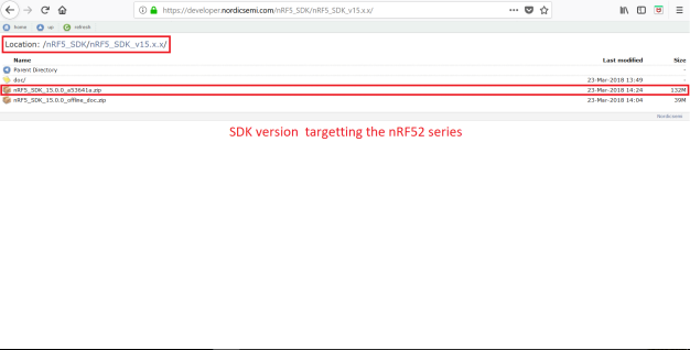
Download SDK v15.0.0 for nRF52 series
b.Create a folder called nordic_semi on your local disk ( it’s preferable to place it as close as possible to the root directory and avoid paths which contain white white spaces), and then extract the .zip-archive file.
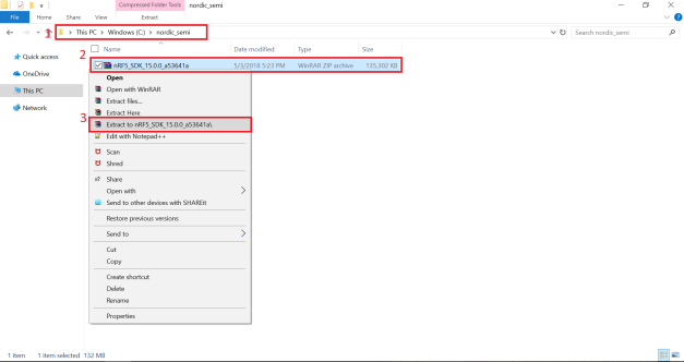
Extract the archived file of the nRF5 SDK locally.
With this the nRF5 SDK has been downloaded and ready to be used by the Seeger Embedded Studio.
2.Download Segger Embedded Studio(SES): Go to
https://www.segger.com/ , and from the
Downloads menu choose
Embedded Studio as shown in the screenshot below.

Download Segger Embedded Studio
In the Downloads page of the Embedded Studio, select Embedded Studio for ARM, then select the download that fits your operating system. SES is supported on Windows , macOS and Linux . ( The example here assumes a Windows machine)
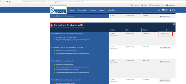
Select Embedded Studio for ARM
3.Install Segger Embedded Studio(SES): Once the download is complete, run the installer file as an administrator and then follow the basic installation steps as shown in the screenshots below.

Run SES installer as admin

SES Install – Welcome Page

SES Install – License Agreement
Select your preferred installation path or leave default options as is
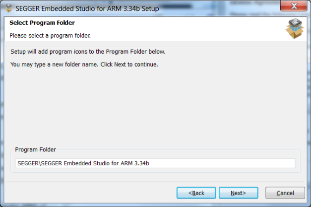
SES Install – Select Installation Path
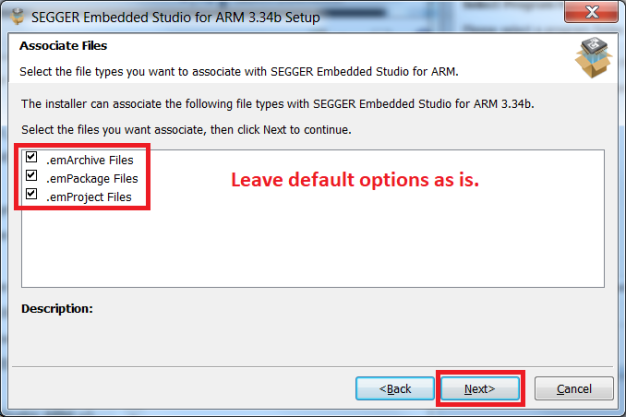
SES Install – Files association
Make sure to install the J-Link device driver to be able to program the development boards.

SES Install – J-Link device driver
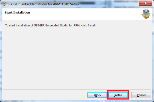
SES Install – Ready to install window
Installation will start. It will take few minutes to finish. Once the installation is done, the following window will pop up. Make sure that the option Start SEGGER Embedded Studio for ARM x.xxx is checked and click Next.
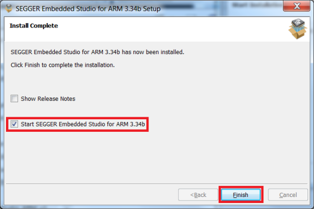
SES Install – Start SES window
Segger Embedded Studio will open with an example hello world program. Leave the program open as we will in the next step request the free of charge license for Nordic Semiconductor development boards and devices.
4.License Segger Embedded Studio(SES) for Nordic devices: SEGGER and Nordic Semiconductor have signed an
agreement in late 2017 that entitles developers to use Segger Embedded Studio with Nordic nRF5x chips for both commercial and non-commercial uses free of charge.
a. In SES, right click on the Solution ‘Hello’ and select Build.

SES Build Project
b. A message indicating that no commercial license is found will pop up. Click onActivate Your Free License as shown in the screenshot below.

Activate your free license
c. The request license window will show up next. You need to enter your first, last name, company name and a valid email address as the license will be sent to you by email as text(Activation Key). The request license window will automatically link the license with the MAC address of your machine.

Request License Window
d. The activation confirmation message pops up indicating that the activation key has been sent to the specified email .
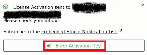
Enter Activation Key Window
e.You should now check your email for your Activation Key, which is a string of text that you need to copy and paste in the activation box and then click Install License.
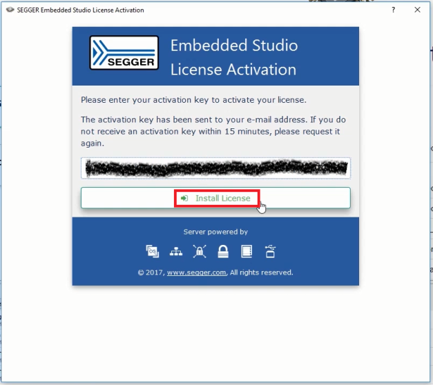
Install License Window
The build process will start and now you have a licensed SES for Nordic Semiconductor devices.
5.Install nRF CPU Support Package: The nRF CPU Support Packages include all supporting files needed to create a complete new project from scratch. It include startup files, memory maps, CPU initialization, etc…. To install the Support Package for the Nordic Semiconductor devices in SES , select Tools > Package Manager…
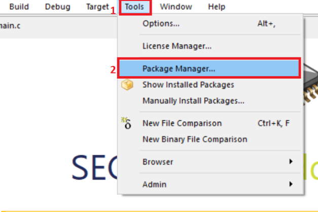
Access Package Manager
The Check for update of Package Manager will show up, click Yes to download the latest packages .
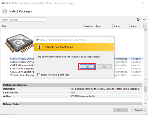
Segger Package Manager – Check for Updates
After the download finishes, type Nordic in the search bar of the Package Manager.

Search for nRF CPU Support Package
Right click on nRF CPU Support Package , select Install Selected Packages and then click Next.

Install nRF CPU Support Package
Click Next in the Summary window. Then Click Finish when the installation is complete.

Support Package Installation Summary Window
6.Setup the CMSIS Configuration Wizard in SES : The the CMSIS Configuration Wizard is a small utility developed in Java which simplifies the process of enabling and disabling modules in the SDK configuration file sdk_config.h. In order to use this utility with SES, you need to register it as an external tool . To do that, open SES, click on File> Open Studio Folder> External Tools Configuration .

External Tools Configuration
The tools.xml file file will open up in the editor. Copy the code below and paste it in the tools.xml exactly as shown in the screenshot below.
<item name=“Tool.CMSIS_Config_Wizard” wait=“no”>
<menu>&CMSIS Configuration Wizard</menu>
<text>CMSIS Configuration Wizard</text>
<tip>Open a configuration file in CMSIS Configuration Wizard</tip>
<key>Ctrl+Y</key>
<match>*config*.h</match>
<message>CMSIS Config</message>
<commands>
java -jar "$(CMSIS_CONFIG_TOOL)" "$(InputPath)"
</commands>
</item>
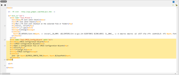
CMSIS Configuration Wizard Integration in SES
Note: You need
Java to be installed on your computer for this utility to work.
With this the SES is setup and ready to be used to develop firmware for the nRF5x Nordic Semiconductor devices and development boards. In the next paragraph we will start our first program in SES. The paragraph after that shows the steps needed to run the examples offered in the next labs.
Your first program
To test that all the steps we did previously are correct and that the Segger IDE is ready for action, we will run a very simple example “Blinky Example” from the nRF5 SDK. The Blinky example toggles the boards LED using the
Board Support Package(BSP) which we will cover in depth in the later labs.
The Blinky Example shows how to configure the GPIO pins as outputs using the BSP library. These outputs can then be used to drive LEDs, as in this example.

Illustration of the Blinky Example workflow
When the application starts, some GPIO pins are configured as outputs to drive the LEDs. The application then loops while toggling the state of one of the LEDs every 500 milliseconds.
1.Browse to the example directory: Using your files browser, head to <nRF5 SDK Installation Path>\nordic_semi\nRF5_SDK_15.0.0_a53641a\nRF5_SDK_15.0.0_a53641a\examples\peripheral\blinky
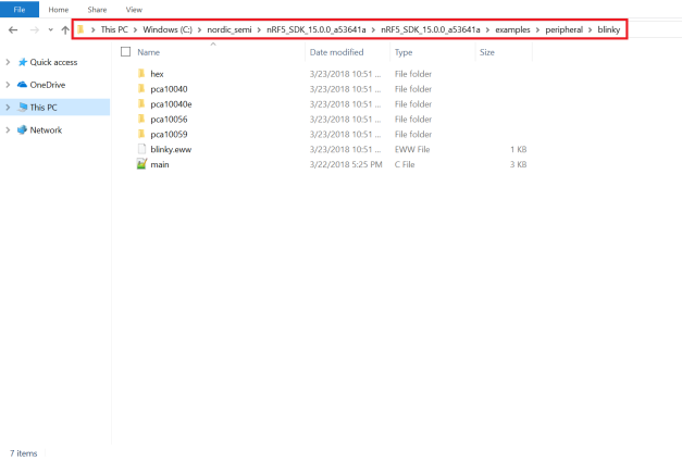
Blinky example directory
2.Select the folder which matches your board ID: In here, we are assuming that the development is done for the
RF52840 DK development board which has the board ID (PCA10056) . Therefore , we will select the pca10056 folder. If you are using a different development board , you need to select a different folder . Refer to
LabA-3for more information on the available boards in the nRF52 series and their board ID number.
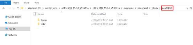
Select the project folder for your development board
3.Select whether to run with/without a protocol stack or advanced feature(s): You will notice that inside almost all board folder examples there are two and sometimes more folders ; one is usually called blank which mean without a supporting interface protocol stack or advanced features . The other folder(s) are usually the name of the supporting protocol stack (s130 softdevice, etc.. )or advanced feature . Since we are not using any protocol stack in this simple example , select blank
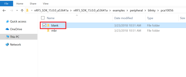
Select the blank directory
4.Select ses folder: Since we are using the Segger Embedded Studio(SES) , select the ses folder to open the SES project file.
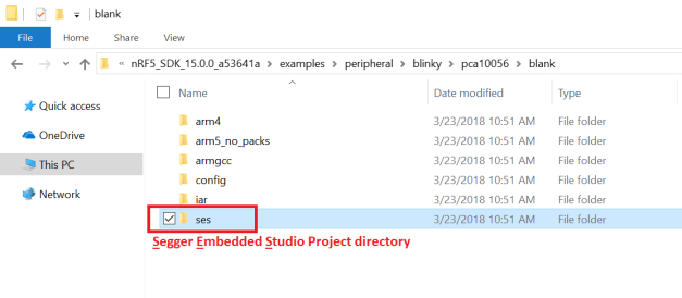
Segger Embedded Studio Project Directory
5.Open the ses project file : Double clink on the blinky_pca10056.emProject file to open the example in SES.

Open the blinky example

blinky example in SES
6.Compile and Build the project : Click Build -> Build blinky_pca10056 or press F7
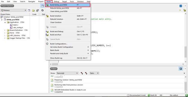
Build Project
The build process will internally invoke the compiler ,assembler and linker and produces the executable blinky_pca10056.hex which will be flashed on the board. It will take few seconds to finish.
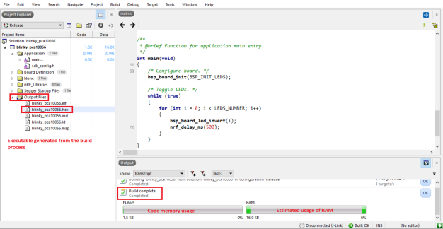
Build Complete
7.Connect the board to the development machine : Connect a Micro-USB cable to your development board (Port J2) and the other end of the USB cable to your laptop/workstation , then switch on your development board (SW8)
8.Download executable on the board : To download the program executable on the board, select Target-> Download blinky_pca10056 . The program will run automatically on the board.
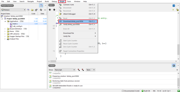
Program the board
You should notice that the board LEDs (LED1-LED4) are toggling now every 500 milliseconds.
9.Modify the code (Optional ): Modify the code and increase the toggling delay from 500 to 2500 milliseconds, then save (Ctrl+S), build and download as done in the previous steps. You should now observe the LEDs are toggling at a much lower rate.
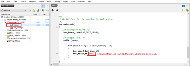
Modify the code
Running Embedded Centric labs and tutorials
In the next labs we will start diving into more hand-on examples and labs. The source code and the SES project files for these labs are available on a
GitHub repository . To be able to run any of these labs, you need to do the steps below
1.Create a directory named embeddedcentric: This directory will hold the projects files of the next labs.
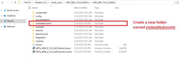
Create embeddedcentric directory

Clone Labs and Tutorials Repository
3.Extract the repository ZIP file: Once the download is complete,extract the content of the compressed file.
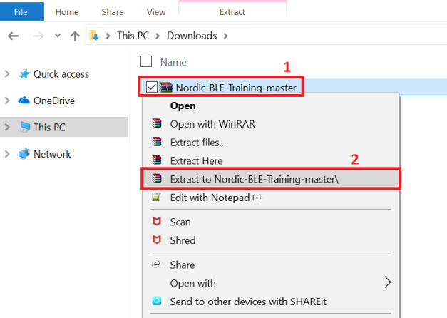
Extract Repository
4.Copy the content into the embeddedcentric folder: Copy all files and directories inside the Nordic-BLE-Training-master folder and paste them in the embeddedcentric directory created recently . Do exactly as shown in the screenshot below , creating or removing directories might cause compilation errors as the search paths for the SDK libraries, drivers and include files might be modified inadvertently.
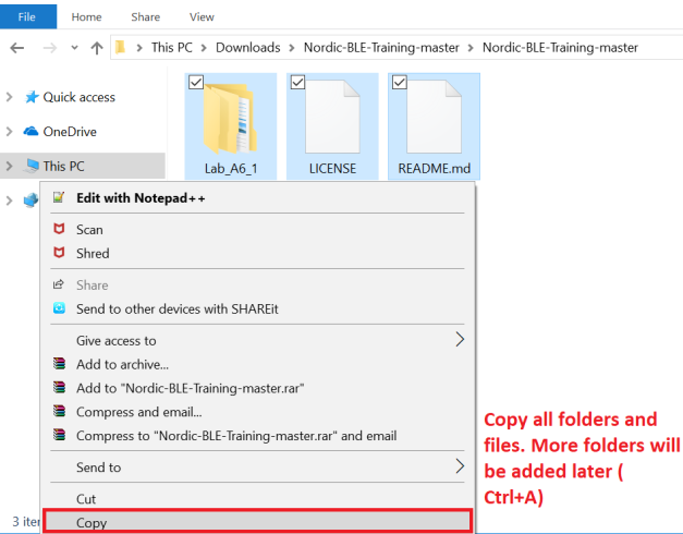
Copy files and directories
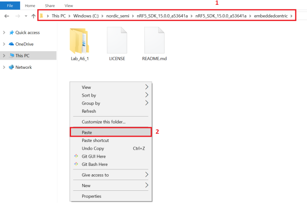
Paste in the embeddedcentric folder
5.Open the ses project file for the desired lab : Double clink on the SES project file that you want to run( Example
LabA6.1)
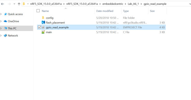
Run the desired lab( Example : LabA-6.1 )
6.Compile and Build the project : Click Build -> Build name of the lab or press F7
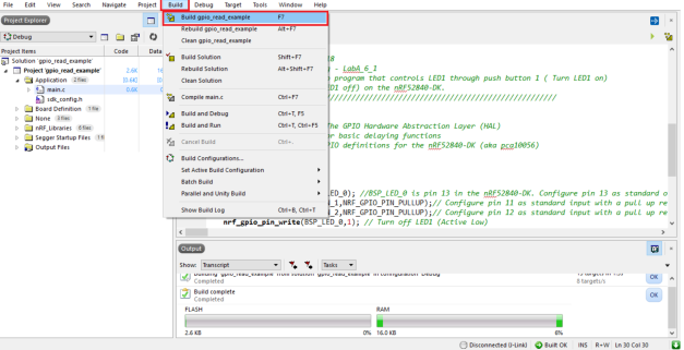
Build Project GPIO
7.Connect the board to the development machine: Connect the USB cable to your development board (Port J2) and the other end of the USB cable to your laptop/workstation , then switch on your development board (SW8). The labs are built for the nRF52840-DK but can be easily modified to tailor any other nRF5x-based development boards or devices.
8.Download executable on the board : To download the program executable on the board, select
Target->
name of the lab . The program will run automatically on the board.
Questões: suporte@smartcore.com.br
Fonte: https://embeddedcentric.com/nrf5x-soc-overview/
Sobre a SMARTCORE
A SmartCore fornece módulos para comunicação wireless, biometria, conectividade, rastreamento e automação.
Nosso portifólio inclui
modem 2G/3G/4G/NB-IoT/Cat.M, satelital, módulos WiFi, Bluetooth, GNSS /
GPS, Sigfox, LoRa, leitor de cartão, leitor QR code, mecanismo de
impressão, mini-board PC, antena, pigtail, LCD, bateria, repetidor GPS e
sensores.


